Logic Circuit Symbols (Digital Electronic)
Electronic circuits that perform operations based on two states (1 - 0) necessary to obtain logical decisions. The logic circuits are composed of elements such as the AND gate, the OR gate, the NOT gate and other combinations of these same circuits.
| Symbol | Description | Symbol | Description | |
|---|---|---|---|---|
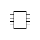 |
Integrated circuit / IC Logic chip + Info |
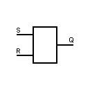 |
Basic memory + Info |
|
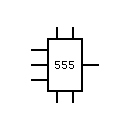 |
555 chronometer Timer IC + Info |
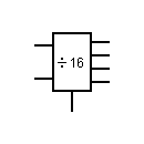 |
4 bit binary counter + Info |
|
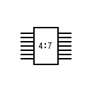 |
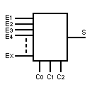
7-segment decoder + Info |
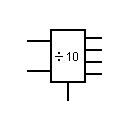 |
Decadic decimal binary coded counter, BCD + Info |
|
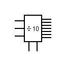 |
Decadico counter with 10 outputs encoded | 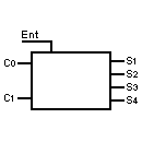 |
Decoder 1 to 4 | |
 |
DAC / D/A Digital to Analog Converter + Info |
 |
DAC Analog to digital converter |
|
 |
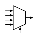
ADC / A/D Analog to Digital Converter + Info |
 |
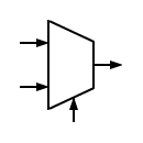
Multiplexer + Info |
|
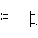 |
Logic adder + Info |
 |
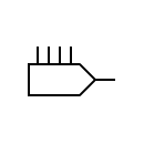
Multiplexer, 2 in 1 out | |
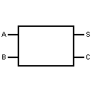 |
Semi-adder + Info |
 |
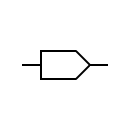
Multiplexer, 4 inputs 1 output | |
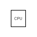 |
Central Processing Unit CPU + Info |
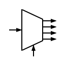 |
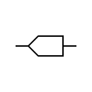
1 input 4-output demultiplexer | |
Display Symbols |
||||
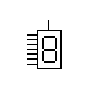 |
7 segment LED display + Info |
 |
Alphanumeric LED indicator 5x7 e.g. letter A |
|
 |
16 segment alphanumeric display + Info |
|||
Logic gate symbol (Digital Electronic)Flip-Flop symbols (Digital Electronic)Amplifier circuit symbolsOther symbols of electronic circuitsDownload symbols |
||||